Ground Fault Indicator Light Wiring Diagram

Electrical Gfci Outlet Wiring Diagram Outlet Wiring Gfci Diy

Wiring Diagram Bathroom With Images Bathroom Lighting

Elegant Wiring Diagram For Light Switch And Plug Diagrams

Diagram Wiringdiagram Diagramming Diagramm Visuals

Tube Light Connection Circuit Wiring Diagram Electrical4u

Gfci Fundamentals Gfci Faqs Gfci How To With Images Gfci

240v lamps are connected in a wye arrangment with the center point connected to ground.
Ground fault indicator light wiring diagram. Please try again later. This feature is not available right now. Ground detector lights are very common well atleast in this part of the world. Wiring a gfci outlet with combo switch outlet receptacle light switch.
In this gfci outlet wiring and installation diagram the combo switch outlet spst single way switch and ordinary outlet is connected to the load side of gfci. Provides 6 probable wiring conditions that are quick and easy to read for ultimate efficiency lights indicate if wiring is correct and indicator light chart is included tests standard 3 wire outlets ul listed light indicates if wiring is incorrect very handy and. But the most common for 240v ungrounded systems uses three lamps light bulbs. There are many different wiring diagrams.
The load terminals on the gfci are not used and the last receptacle is wired directly to the circuit source. A wiring diagram is a simplified standard photographic representation of an electrical circuit. This diagram illustrates the wiring for multiple ground fault circuit interrupter receptacles with an unprotected duplex receptacle at the end of the circuit. Collection of ground fault receptacle wiring diagram.
Methods for wiring gfci receptacle outlets. House wiring diagram for gfi. The light on off operation can be controlled through the gfci switch while the ordinary outlet is directly connected to the gfci load terminals. It shows the components of the circuit as streamlined shapes and the power as well as signal connections in between the devices.

12v Dc Power Supply Without Transformer With Images Circuit

A Good Gfci Outlet Will Help Keep Your Home And Outdoor Area Safe

2 Way Light Switch With Power Feed Via Switch Two Lights With

Led Indicator Lights Wiring Diagram With Images Motorcycle

Baomain Gfci Outlet Receptacle 20amp 120vac 60hz Weatherresistant

How To Install A Gfci Outlet With Images Gfci Home Electrical

Image Of Wiring Diagram For House Light A Simple Two Way Switch

Unique Wiring Diagram For Car Trailer Socket With Images

Pin By Terry Pennington On Electrical Wiring Electrical

Wiring For Sabs South African Bureau Of Standards 7 Pin Trailer

Pin On Breakers Load Centers And Fuses
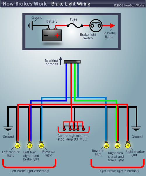
Brake Light Wiring Diagram Howstuffworks

Pin On Home Design
