Grasslin Time Clock Wiring Diagram
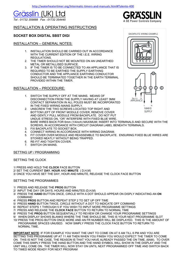
Grasslin Uk Ltd Installation Amp Operating Instructions

Od 6004 Grasslin Timer Wiring Diagram Download Diagram

9e3b097 Grasslin Timer Wiring Diagram Free Download Wiring Resources

Grasslin Digi 56 72 Manual Signaturelasopa

Grasslin Fm1 Instruction Manual Manualzz

T 49f Wiring Diagram Swapping Timer On True T49f Freezer From
Auto voltage 120 240 vac 60 hz q models 50 60 hz electrical ratings.
Grasslin time clock wiring diagram. 40 amp resistive 120 240 vac 1 hp 120 vac 2 hp 240 vac. Grasslin 40a defrost timer wiring diagram wiring diagram is a simplified usual pictorial representation of an electrical circuit it shows the components of the circuit as simplified shapes and the power and signal friends amongst the devices. 23 hours 45 minutes ratings input voltage. Time initiated time terminated grasslin mode selection wiring diag.
Real time clock face for quick easy and accurate setting min on off time. Wiring the timer clock on a grasslin talento 111 for my pool motor newbie help ne thanks for responses based in jhb the timer still works if i manually move the dial so i am wondering if there is possibly a connection wire i have not installed to activate the clock the ch i 3 slot is empty as per pics so anyone familiar with this. Figure 4 7 5. Dtav replaces over 40 models.
Time initiated pressure terminated separate pressure switch required see instructions time initiated remote temperature or pressure terminated cross ref. Control elements start program input hand switch set time end program input enter pulse cycle select day s reset of the week delete switching time set minutes month year set hours day year summer time winter time switchover 4. Set mode selection see s1 dip switch table and instructions below.

Need Confirmation On The Wiring Of This Digital Timer
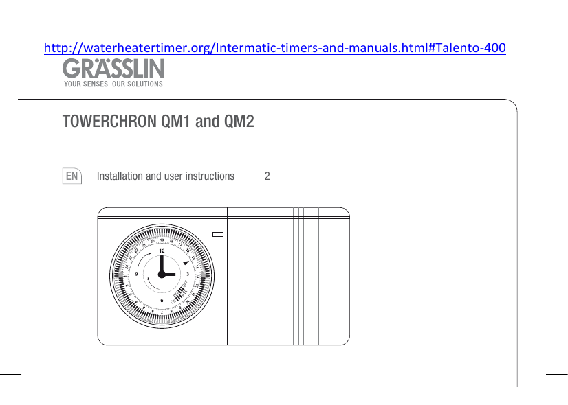
Towerchron Qm1 And Qm2 Installation And User Instructions

Rh 2907 Grasslin Time Clock Wiring Diagram Free Diagram
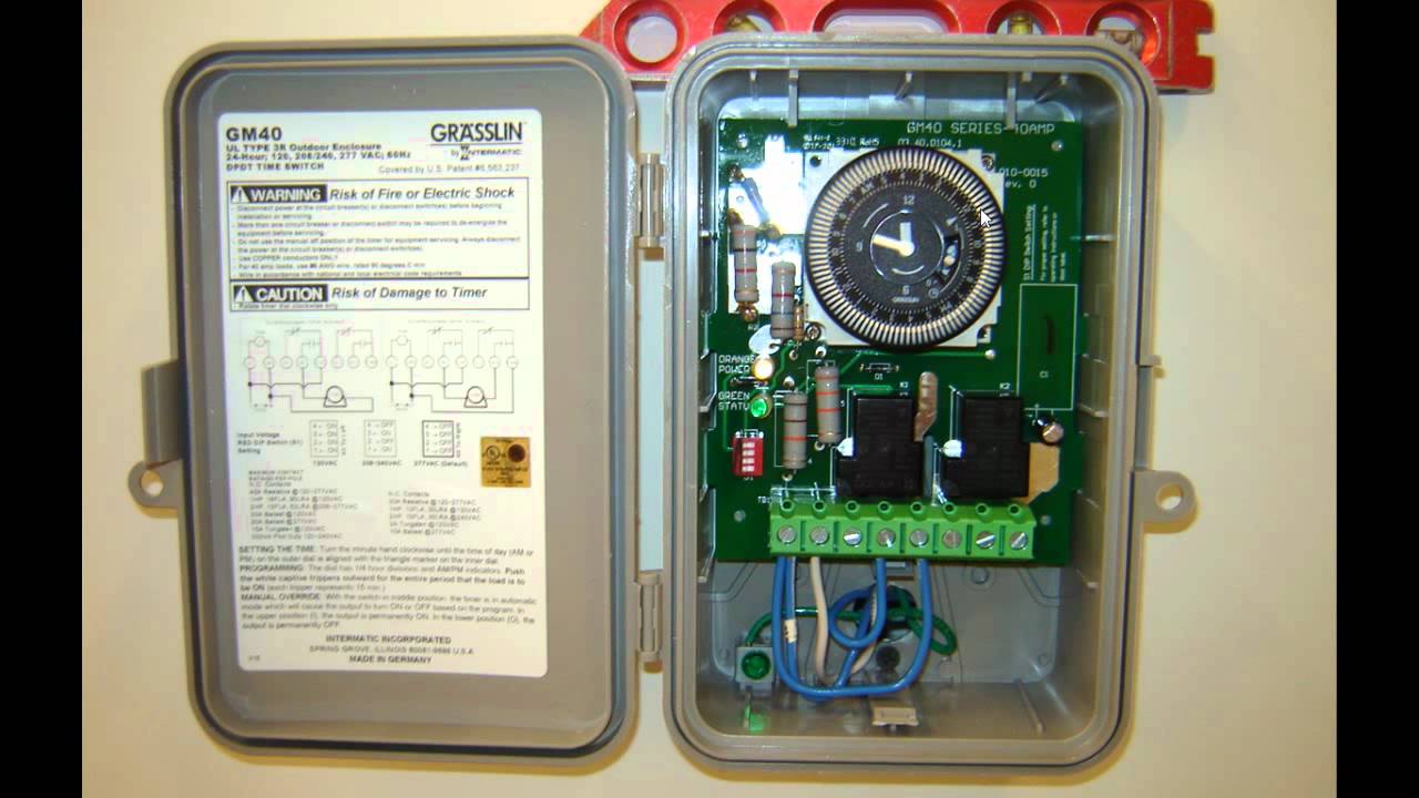
Gm 40 Time Clock Youtube

How To Wire Timers

How To Wire Dt 1440 Timer
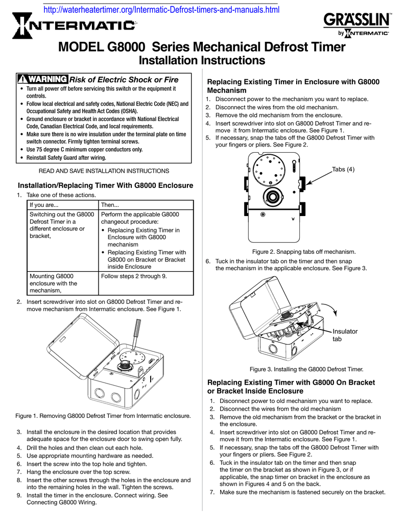
Model G8000 Series Mechanical Defrost Timer Installation

How To Wire T106 Timer
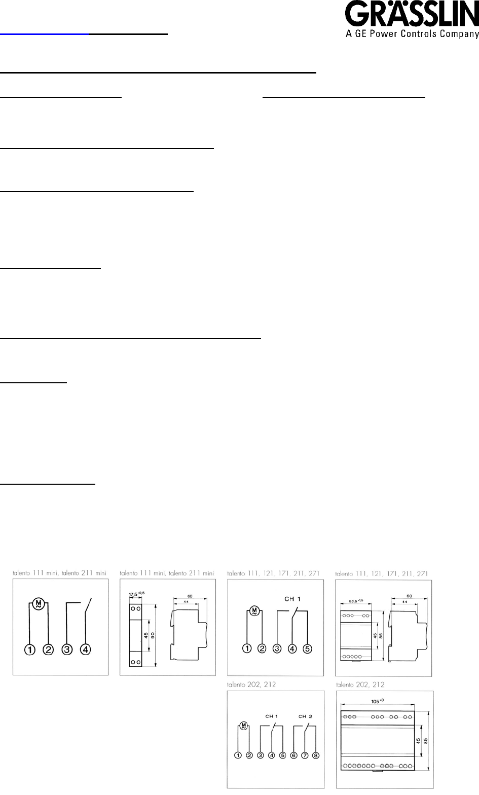
Grasslin Uk Ltd Talento 111 121 171 211 271 202 212
Combi Boiler Timer Wiring Help Diynot Forums

24 Volt Programmable Timer

Grasslin Time Clock 110v 16a 24hr 5 Pin 60hz Fm 1 Stuz L

Wire Diagram For Timer Wiring Diagram
