Graco Wiring Diagram

312932a Magnum Pump Kit For X5 X7 Lts 15 And Lts Graco Inc

312067e Reactor Electric Proportioners Electrical Graco Inc
Http Www Graco Com Content Dam Graco Tech Documents Manuals 309 309226 309226en M Pdf
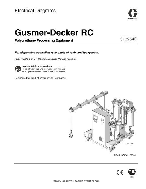
313264d Gusmer Decker Rc Electrical Diagrams Graco Inc
Https Www Graco Com Content Dam Graco Tech Documents Manuals 309 309574 309574en P Pdf
Http Www Graco Com Content Dam Graco Tech Documents Manuals 312 312786 312786en J Pdf

Page 6 shows the recommended wiring schematic using graco supplied cables valves and pulsers.
Graco wiring diagram. 1095 1595 mark v series b motor ti7346a green ground on off switch black digital display white power plug black green ground pressure transducer 14a 10a switch 1595 mark v potentiometer watchdog 311365h. Wiring diagram wiring diagram 695 795 lo boy series b. Refer to table 1 2 and 3 to determine the required sys tem configuration sensor configuration and wiring diagram to use to setup your system. Sensor wiring diagrams fig.
Save these instructions. Not for use in explosive atmospheres. Information for operations replacement parts troubleshooting technical data and warranty information for graco products can be found in the instruction manuals. 16 on the following pages show typical injector divider valve and dual line lubri cation system configurations.
Pages 7 and 8 show the alternative wiring schemat ic using customer supplied cables with graco. The exclama tion point symbol alerts you to a general warning and the hazard symbols refer to procedure specific risks. See page 4 for a list of models and maximum working pressures. A hand crimp tool is available from graco.
Important safety instructions read all warnings and instructions in this manual. Wiring diagram on off switch replacement 120 vac wiring diagram on off switch white 826031 a 826032 a capacitor m black power green plug red pressure black transducer from motor yellow ti2159a potentiometer fig. 795 hi boy series c. Wiring diagram m motor pump power or solenoid v electric vent valve for injector based systems fig.
Glc 2200 wiring connector kit used to interface the glc2200 lubrication controller to pump and pump accessories. 10 and wiring diagrams fig. Warnings 4 312667l warnings the following warnings are for the setup use grounding maintenance and repair of this equipment.
Http Www Graco Com Content Dam Graco Tech Documents Manuals 3a1 3a1244 3a1244en F Pdf

Graco Wiring Diagram Hamra Arabians De
Https Www Graco Com Content Dam Graco Tech Documents Manuals 3a4 3a4649 3a4649en F Pdf

308342n Tex Spray Compact Graco Inc

Graco Promix 2ks Manuals Manualslib
Https Www Graco Com Content Dam Graco Tech Documents Manuals 3a4 3a4128 3a4128en C Pdf
Http Www Graco Com Content Dam Graco Tech Documents Manuals 3a4 3a4399 3a4399en A Pdf

Graco Ultra Max Ii 490 Manuals Manualslib

Page 36 Of Graco Inc Paint Sprayer 261820 User Guide Manualsonline Com

Graco Mark V Manuals Manualslib
Http Www Graco Com Bin Findmanual Manual 334659